SENDING DATA
|
|
SENDING DATA |
|
Data cannot be sent directly to the PSG without first setting up the 6522 (Versatile Interface Adapter (VIA)). The 6522 is the input/output device of the Oric. It is not dedicated to sound though, but to many other areas as well. So care must be taken when sending data to ensure that the Keyboard, Cassette ports, Printer ports and interrupts are not corrupted in the process.
The PSG or AY-3-8912 Programmable Sound Generator is not a memory mapped device. "Memory mapped" means that a device can be addressed within the ORICs memory. Instead, the PSG is accessed through the 6522 which is memory mapped and falls between the range of memory locations #0300 and #030F hexadecimal.
|
6522 Versatile Interface Adapter (VIA) Table 1.0 |
Although the PSG only connects to around half the pins on the VIA, in so doing it affects almost all the registers inside the VIA. The Data Bus connects directly to I/ORA whilst two control lines, BC1 and BDIR connect to CA2 and CB2 which are in actual fact control lines for I/ORA and I/ORB respectively. The logic levels of these control lines will change the way the PSG treats the Data Bus (I/ORA) as illustrated in Table 3.0. Remember that I/ORA is also the Printer Port (Commonly used for Joystick interfacing (PASE/IJK)). In order to send a volume of 10 to Channel A of the PSG, a routine must ensure that both the logic levels on the control lines are zero (Inactive) before placing the number 8 (Channel A Volume Register Number) onto the Data Bus (Location 030F). Both CA2 and CB2 are then set. The PSG will then accept the data as a register number. The Lines must then be cleared again (to zero) in order that any further data placed onto the Bus will not be treated as another Register number. Next, the value of 10 (Volume level) is placed into 030F before sending CB2 high. The PSG will then treat the new data as register data. Finally, CB2 is cleared to set the state to inactive again.
|
||||||||
|
Memory Location |
Mnemonic |
Description |
|||||||
|
0300 |
I/ORA |
Port B (Various functions) |
|||||||
|
0301 |
I/ORB (With Handshake) |
With Handshake |
|||||||
|
0302 |
DDRB |
Data Direction Register B |
|||||||
|
0303 |
DDRA |
Data Direction Register A |
|||||||
|
0304 |
T1C-L |
Read/Write Counter Low T1 |
|||||||
|
0305 |
T1C-H |
Read/Write Counter High T1 |
|||||||
|
0306 |
T1L-L |
Read/Write Latch Low T1 |
|||||||
|
0307 |
T1L-H |
Read/Write Latch High T1 |
|||||||
|
0308 |
T2C-L |
Read Counter/Write Latch T2 |
|||||||
|
0309 |
T2C-H |
Read Counter/Write Latch T2 |
|||||||
|
030A |
SR |
Shift Register |
|||||||
|
030B |
ACR |
Auxiliary Control Register |
|||||||
|
030C |
PCR |
Peripheral Control Register |
|||||||
|
030D |
IFR |
Interrupt Flag Register |
|||||||
|
030E |
IER |
Interrupt Enable Register |
|||||||
|
030F |
I/ORA (No Handshake) |
Printer/Sound/Joystick |
|||||||
|
AY-3-8912 Programmable Sound Generator (PSG) Table 2.0 |
This all takes up a lot of time. There are however, ways to shorten the sequence. One needs though, to take a more in-depth look at the actual logic levels that need to be performed. Both CA2 and CB2 'Control' appear within the PCR. CA1 and CB1 also appear here (but these are generally both set to one) as illustrated in Table 3.1. The logic levels of these control lines can be altered in many ways as shown in Table 4.0. In addition to the Peripheral Control over CB2, this is also the same line fed to by the Shift Register. This Register can also be used to good effect, as I will move onto shortly. If the 6522 is removed out of the context of the ORIC, CA2 and CB2 are actually handshaking lines for I/ORA and I/ORB respectively. Therefore, If CB2 is set to Handshake Output in PCR, then any access to Port B (I/ORB) will have the knock on effect of setting CB2. This can speed up transfers greatly. |
||||||||
|
Register Number |
Bits Used |
Description |
|||||||
|
00 |
B0-7 |
Channel A Pitch Low |
|||||||
|
01 |
B0-3 |
Channel A Pitch High |
|||||||
|
02 |
B0-7 |
Channel B Pitch Low |
|||||||
|
03 |
B0-3 |
Channel B Pitch High |
|||||||
|
04 |
B0-7 |
Channel C Pitch Low |
|||||||
|
05 |
B0-3 |
Channel C Pitch High |
|||||||
|
06 |
B0-4 |
Noise Pulse Width |
|||||||
|
07 |
B0-6 |
Status Register |
|||||||
|
08 |
B0-4 |
Channel A Volume |
|||||||
|
09 |
B0-4 |
Channel B Volume |
|||||||
|
0A |
B0-4 |
Channel C Volume |
|||||||
|
0B |
B0-7 |
Envelope Period Low |
|||||||
|
0C |
B0-7 |
Envelope Period High |
|||||||
|
0D |
B0-3 |
Envelope Cycle Register |
|||||||
|
0E |
B0-7 |
Keyboard Column Register |
|||||||
|
BC1 (CA2) & BDIR (CB2) lines to the PSG Table 3.0 |
Memory Location 030C where CA2/CB2 appear in the PCR Table 3.1 |
||||||||
|
CA2 |
CB2 |
Action/State |
Bit Positions |
Description |
|||||
|
0 |
0 |
Inactive |
B0 |
CA1 Control (Set to 1) |
|||||
|
0 |
1 |
Write Data |
B1-3 |
CA2 Control (Shown in Table 4.0) |
|||||
|
1 |
0 |
Read Data |
B4 |
CB1 Control (Set to 1) |
|||||
|
1 |
1 |
Write Register Number |
B5-7 |
CB2 Control (Shown in Table 4.0) |
|||||
|
PCR CA2/CB2 Logic Level Control Table 4.0 |
There are other ways as well as this. "Pulse mode" may also be set up and in so doing; CB2 or CA2 can switch on and off automatically just by the respective register access. The Shift Register, for which was never intended for any function on the Oric, can be put to good use. The programmer can set this up to mode 100 (Binary). This shifts out the contents of the register without corrupting the data in it. Like a 'Rotate Right' 6502 instruction (ROR), each consecutive bit will be shifted onto CB2. The speed of the rotation is dependent on Timer 2. Setting this to 1 and placing 10101010 Binary into the Shift register will continuously shift out a pulse onto CB2 at 500Khtz! If the Register number is set up before hand, this technique can create a virtual PSG register in #030F or #0301. |
||||||||
|
Nibble Number |
CA2/CB2 Level Description |
||||||||
|
0 |
Input |
||||||||
|
1 |
Input |
||||||||
|
2 |
Input |
||||||||
|
3 |
Input |
||||||||
|
4 |
Handshake Output |
||||||||
|
5 |
Pulse Output |
||||||||
|
6 |
Low Output |
||||||||
|
7 |
High Output |
||||||||
This is a very useful technique for sending Sample Data to the Sound Chip. Note that by making the shift register take over CB2 logic levels, changing the level of CB2 in PCR will have no effect. This is useful since Euphoric, the Oric Emulator for the IBM-PC cannot simulate the Shift register (Every machine would be required to be a PENTIUM!). So setting CB2 in PCR after the Shifting has been set up means that an Oric Program can play samples regardless of whether it is on the Emulator or the real thing.
Note also that some ORIC ATMOS machines, not all mind you, allow CB2 to be set permanently high in order to send lots of data to a single PSG register. Others crash out when this is attempted. The Emulator supports this.
The aforementioned couple of techniques are really only useful for sending a vast amount of data to just one register. To send to multiple registers and (As Sound Tracker does) to shorten the time in so doing, one has to look at the logic levels over the cycle of sending information to a register.
|
Standard Control line settings to send to one specified Register Table 5.0 |
As shown in Table 5.0, sending data the tried and tested way is slow, even if the program writes a specific value to the Registers rather than checking their existing values. The problem is with the inactive states. Since the sound quality will not be effected by random PSG Register selecting so long as by the time valid sample data is sent, the proper register has been selected, it is quite feasible to cut out the last line. Table 5.1 Illustrates this. These are at present all the techniques that I have tried. |
||
|
CA2 Logic Level |
CB2 Logic Level |
Procedure |
|
|
0 |
0 |
Place Register into 030F |
|
|
1 |
1 |
Latch as Register Number |
|
|
0 |
0 |
Set lines Inactive again |
|
|
0 |
0 |
Place Data into 030F |
|
|
0 |
1 |
Write data to PSG |
|
|
0 |
0 |
Set lines inactive again |
|
|
SOUND TRACKER Sample Send Routine Table 5.1 |
There is another technique, one that surprisingly I have never tried! Using the aforementioned SR Technique, also set CA2 to handshake mode, therefore, theoretically any data sent to 0301 will be a handshake and therefore set CB2 and CA2 both high (Register data to 0301). Just writing to 030F will be with no handshake and thereby treated as Register Data. The trickiest part is in setting SR up to synchronise with the rise of CA2 when 0301 is accessed. |
||
|
CA2 Logic Level |
CB2 Logic Level |
Procedure |
|
|
1 |
1 |
Place Register into 030F |
|
|
0 |
0 |
Set lines Inactive again |
|
|
0 |
0 |
Place Data into 030F |
|
|
0 |
1 |
Write data to PSG |
|
|
1 |
1 |
Latch as Register Number |
|
Although ones own machine code tends to be faster than the ROM routines written to access the PSG, the procedures in ROM can still be very useful to set up certain aspects of the PSG.
The routine addresses given below are for the Oric Atmos only
#F590 - Place the register number in the accumulator and the register data in the X-register then call this routine to send it to the PSG.
#FA86 - Sends a table containing 14 register values (Misses out the Keyboard column register) to the PSG. Place the table start Address in registers X (Low) and Y (High) before calling this routine.
Finally, A fuller description of the PSG registers is in order.
|
PSG Registers Table 6.0 |
The first six registers of the PSG form three 14 bit entities that specify the frequency or pitch of the three tone channels. Each second register (01, 03 and 05) out of the six hold the most significant four bits in there lower nibbles. The upper nibble is not used. Frequencies range from 15.26Hz to 62.5Khz or over 9 Octaves. Register number 06 specifies a noise pulse width amount from zero to thirty one. The noise is not a true channel since it cannot play by itself. It must be told to act upon one of the three tone channels in order that it is audible. Control over which channels should be effected by noise is selected in Register 07, the status register. Bits zero to two select which tone channels are to be switched in and out. Note that when a bit is zero, that particular channel is switched on whilst if set to one, the channel is switched off. Bits three to five select the Tone channels that the noise generator will effect. This follows the same format as the Tone switching. |
||
|
Register Number |
Bits Used |
Notes |
|
|
00 |
B0-7 |
Channel A Pitch Low |
|
|
01 |
B0-3 |
Channel A Pitch High |
|
|
02 |
B0-7 |
Channel B Pitch Low |
|
|
03 |
B0-3 |
Channel B Pitch High |
|
|
04 |
B0-7 |
Channel C Pitch Low |
|
|
05 |
B0-3 |
Channel C Pitch High |
|
|
06 |
B0-4 |
Noise Pulse Width |
|
|
07 |
B0-6 |
Status Register |
|
|
08 |
B0-4 |
Channel A Volume |
|
|
09 |
B0-4 |
Channel B Volume |
|
|
0A |
B0-4 |
Channel C Volume |
|
|
0B |
B0-7 |
Envelope Period Low |
|
|
0C |
B0-7 |
Envelope Period High |
|
|
0D |
B0-3 |
Envelope Cycle Register |
|
|
0E |
B0-7 |
Keyboard Column Register |
|
Bit six selects whether the I/O port is for input (0) or Output (1). This port is Register 0E which the Oric uses to select the keyboard Column. Bit seven is not used.
Register numbers 08, 09 and 0A specify what controls the volume of each tone channel. If bit four is set, then the volume is controlled solely by the envelope generator otherwise the lower four bits specify the volume level.
Registers 0B and 0C control the period of the Envelope by forming a 16 bit period entity. Register 0C is the MSB of the entity.
useful ones.
|
|
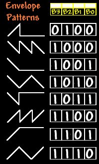
Register 0D controls the shape of the Envelope. Of the 8 Bits in the location, only the lower 4 are actually used. In addition, out of the 16 values attainable from 4 bits, only 8 useful ones exist. The rest repeat the same patterns of the 8. These 8 are shown on the table to the left. |